
![]()
Overview of the Optical Phased Array (OPA) research in Laboratory for Advanced Integrated Circuits and Systems (LAICS) at the University of Rochester developed from 2018 to present.
Table of Contents
What is an OPA in one sentence?
A solid-state electronic-controlled high-speed beamsteering photonic circuit.
Research Objective
The objective of my research is to design optical phased array (OPA) circuits and systems capable of rapid beamsteering and efficient information transmission. While the wave diffraction and interference nature of phased arrays enable light-speed beamsteering, the design, implementation, control, and analysis of OPAs remain significant engineering challenges. Once it succeeds, it will represents a fundamental advance in LiDAR and free-space optical communication. It would also improve our abillity to precisely manipulate light beams in a finer scale, enabling new applications for sensing, 3D-printing and light-matter interactions.
Challenges
OPA beamsteering requires active control and is challenging to accomplish because it demands seamless coordination between the photonic chip (PIC) and its peripherial electronics, akin to a harmonic symphony. A control program acts as a symphony conductor, guiding the system to adhere to its calibration data and steering coefficients while minimizing crosstalk within the photonic chip. Calibrations serves as the symphony’s rehearsal, ensuring optimal performance, and only through the fine analysis program can the best calibration data be well-tuned during these rehearsals.
Project Timeline
2016-2019 The OPA project was first initiated in 2016 by Dr.Francis Smith for concept verification. I joined the group in Fall 2017 as a M.S student, working closely with Dr. Smith on various aspects, including OPA device and circuit-level simulations, electronics design, test setup construction, and automation. By late 2018, our team successfully demonstrated OPA beamsteering, which led to securing funding to advance the project.
2019-2024 After Dr. Smith’s graduation in 2019, I transitioned into a Ph.D. student to continue and expand the project. I introduced new ideas and tapeouted new PICs through various foundries(IMEC, AMF and AIM). My research has focused on enhancing the OPA system’s performance metrics, including beamsteering speed, range, accuracy, and power efficiency. Meanwhile, I developed customized electronics to scale the system down from a bench-top setup to a portable version while also exploring OPA-based free-space optical communication applications.
Project Demo
The following sections demonstrate an OPA system, including its beamsteering capabilities and spatial multiplexing performance.
Photonics
Our integrated OPA circuits are developed on a silicon photonics platform. Illustrated below is a 4x4 OPA featuring a subarray configuration.
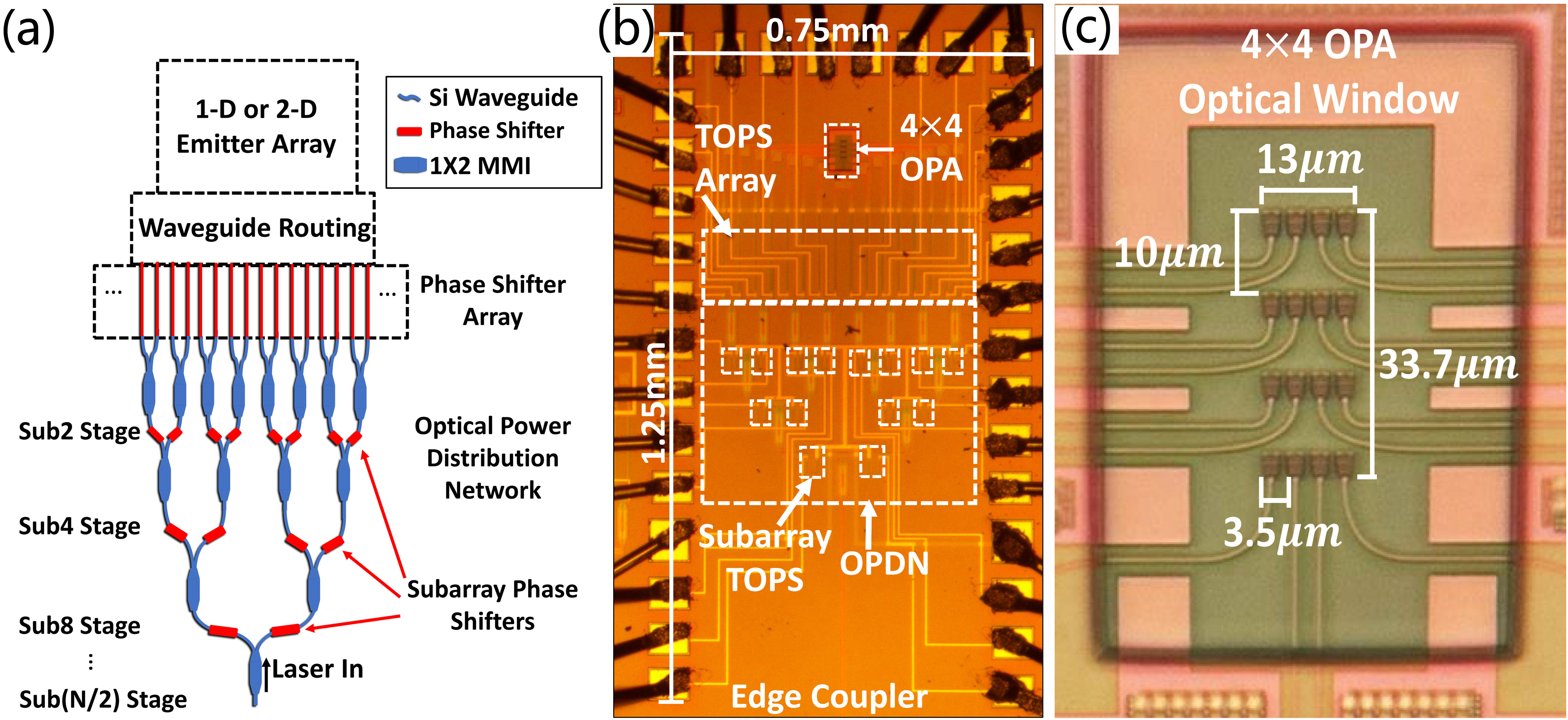
Fig: (a) OPA design illustration. (b) Micrograph of the prototype OPA chip. (c) OPA aperture region.
Testsetup Evolution
Active controls are required for beamsteering in the PIC. To achieve this, we developed two generations of benchtop test setups and two generations of OPA drivers/packages to integrate and control the OPA PICs effectively. The images below illustrate the evolution of our test setups.
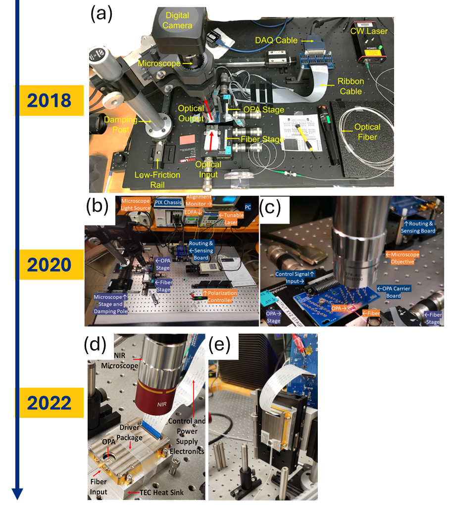
Fig: (a) NI-DAQ based test setup in 2018. (b)(c) NI-PXI-DAQ based test setup in 2020. (d)(e) Test setup based on customized hardware in 2022.
2018 Developed a system with 32-channel analog outputs and automation capabilities to control the OPA chip.
2020 Upgraded to a 64-channel system featuring analog inputs and outputs for OPA chip control. The analog inputs provided electrical feedback, enabling more precise control. The system achieved an update rate of 2 ms per beamsteering operation.
2021-2022 Designed and implemented customized hardware, including a driver board and an MCU board, alongside a 64-channel analog input/output package for OPA chip control. The package incorporated a temperature control system using a TEC unit and an in-house fiber attachment solution, eliminating the need for translational stages. The MCU board supported both standalone and PC-based control modes. The new system achieved an update rate of 350 microseconds per beamsteering operation, offering a 5x improvement in speed compared to the previous system.
Electronics
We developed our customized hardware as shown in the following:
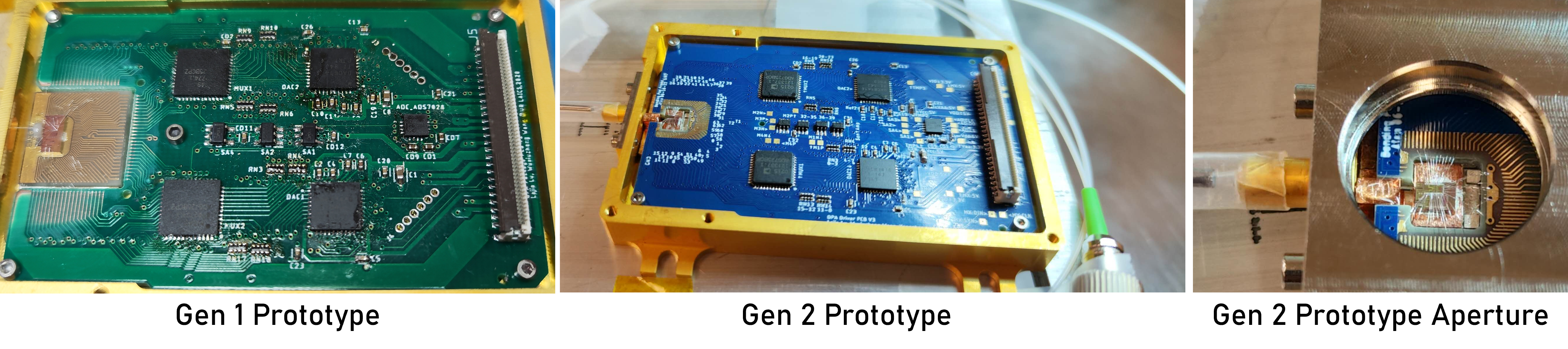
Fig: (a) Gen1 driver board and package in 2021. (b) Gen2 driver board and package in 2022. (c) OPA region.
The driver board delivers all analog inputs and outputs required for operation. Digital controls and power supplies are routed through a flex cable connected to the MCU board.
Beamsteering
By integrating photonics and electronics, we enable both beamforming and beamsteering capabilities.
Simulations
OPA beamsteering simulations using MATLAB.
Fig: Simulated beamsteering in azimuth and elevation directions.
Under Microscope
Using a microscopic imaging system, we can accurately measure the beam pattern at low optical power while effectively eliminating unwanted light.

Fig: OPA beamsteering in azimuth and elevation directions under the microscope.
![]()
![]()
Fig: real-time OPA beamsteering under the microscope. The IR camera frame rate is “sync” to the beamsteering speed, such that the ‘U’ and ‘R’ letters are displayed.
Free-Space Optical Communication
Rapid beamsteering and high-bandwidth optical channels enable the transmission of massive data to multiple optical receivers through spatial multiplexing within the beamsteering range. This technology holds significant potential for applications in data centers and space environments, where the effects of air turbulence are minimized.
Setup
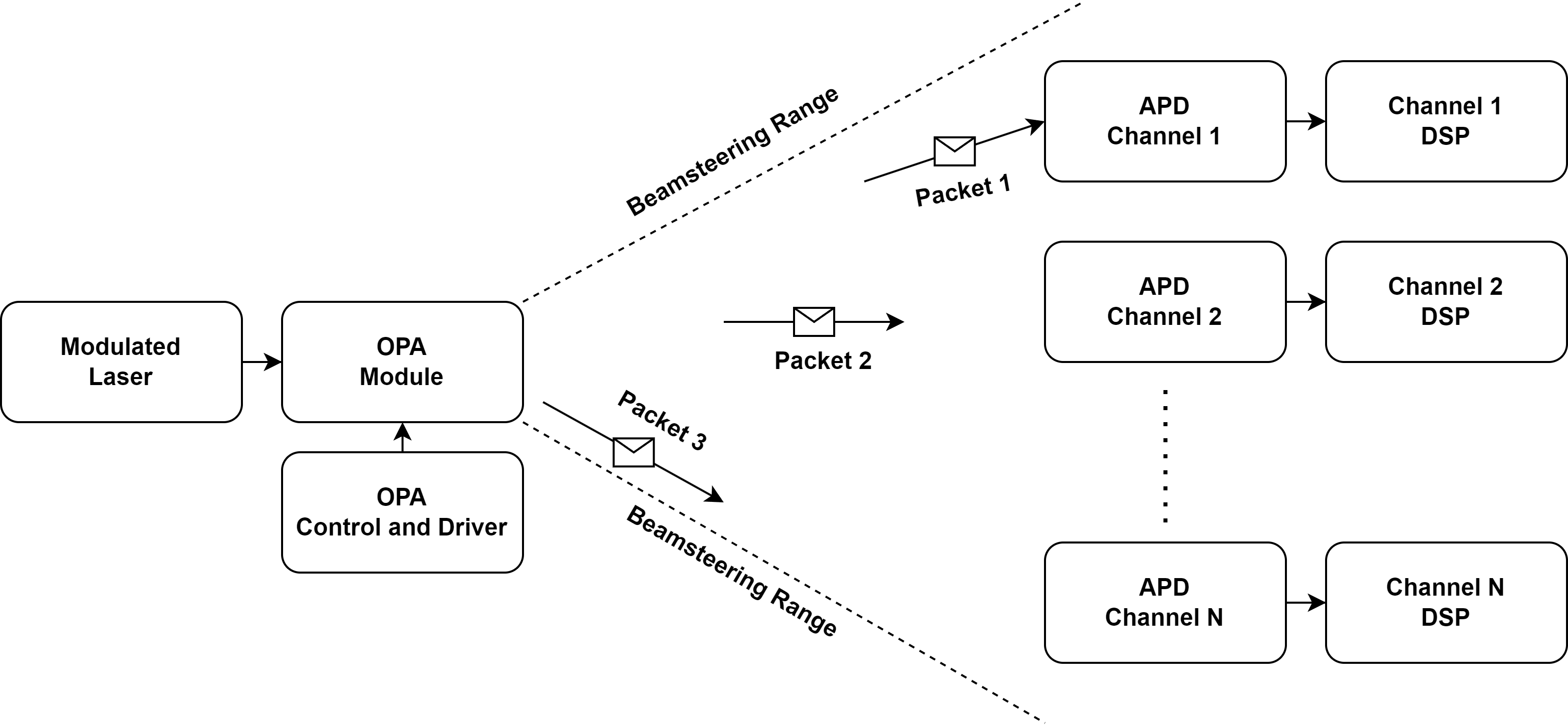
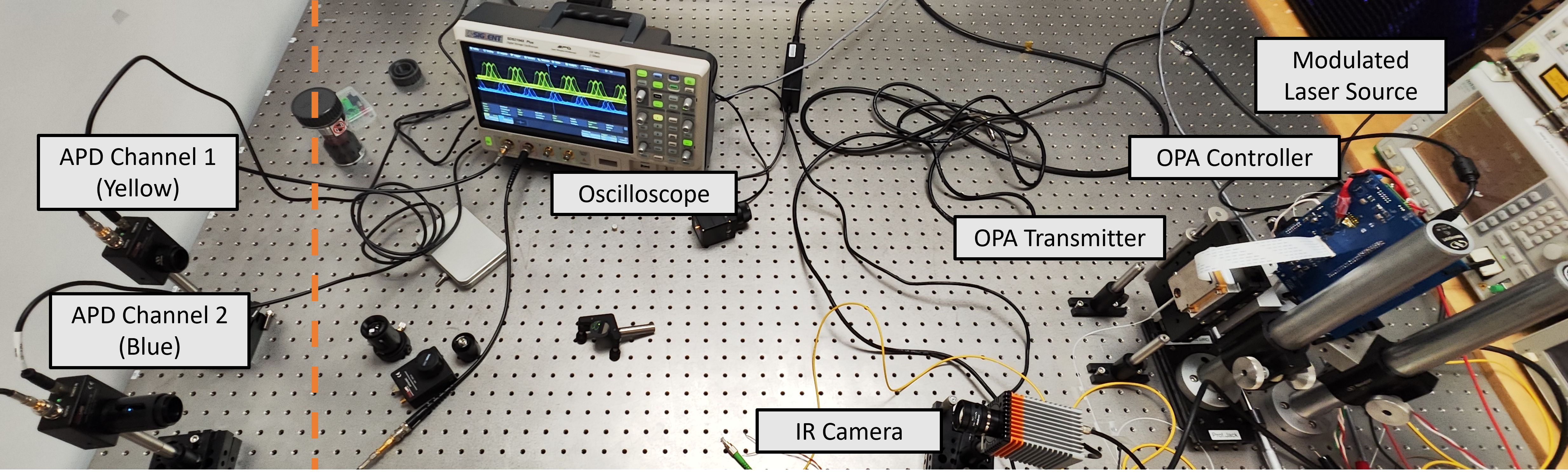
Fig: The top diagram illustrates the concept of free-space optical communication through spatial multiplexing. The middle image presents the demonstration test setup. The bottom-left animation illustrates beamsteering across two APD detectors, as captured by the IR camera. To the right, the oscilloscope displays the modulated signals from the two APDs.
Multiplexing
Once the detector positions are known, intermediate beamsteering steps can be skipped, allowing multiplexing between two detectors in a single step.
Fig:Left animation illustrates beam multiplexing bwtween two APD detectors. To the right, the oscilloscope displays the modulated signals from the two APDs.
Acknowledgments
This research is partially supported by NSF grants ECCS-1842691 and IIS-1722847. We also acknowledge funding support by L3Harris Space and Airborne Systems and CEIS. We would like to thank J.Daniel Newman, Andrew Sacco, and Daniel Sundberg for providing resources and support to our works; Dr. Wenhui Hou, Dr. Tara Peña, and Professor Stephen Wu for PIC wirebondings; Dr. Jingwei Ling and Professor Qiang Lin for equipment; Yujia Yan and Ge Zhu for enlightening discussions; IMEC for PIC fabrication.
Special thanks to my colleagues for their invaluable contributions:
- Dr. Francis Smith for all the collaborations on the OPA project.
- Lejie Lu for assisting with the driver board PCB design.
- Shuangyang Li for migrating the test setup from LabVIEW codes to C-based codes.
- Lydia King for her dedication to the design of the MCU board and the development and testing of low-level SPI and QuadSPI functionalities.
- Dr.Ming Gong for exploring innovative fiber attachment solutions.
- Yongchao Liu for providing support with electrical design.